Circuit Diagrams
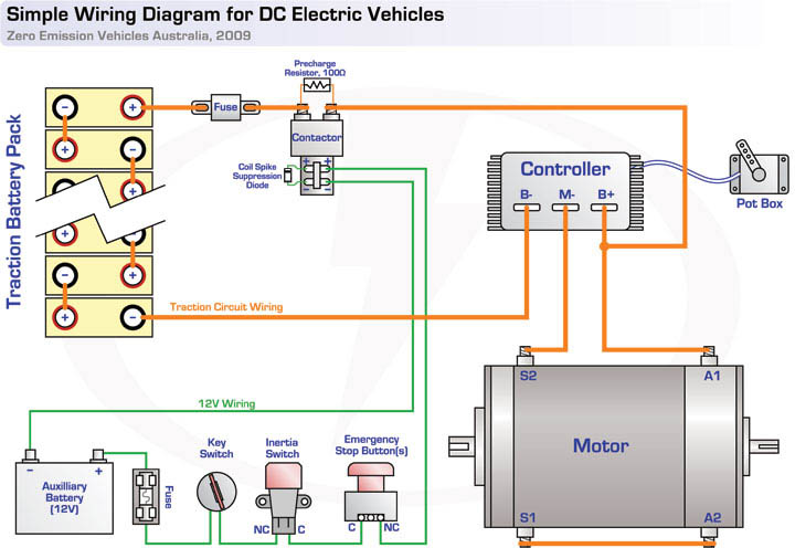
The diagram above shows the "bare bones" wiring for the traction circuit in a typical electric vehicle, with a series DC motor and controller.
- Potbox wiring will vary between controllers – please consult your controller's documentation if unsure.
- AC systems will be similar, but will have three separate wires going to the motor instead of two – refer to your controller's documentation for more information.
- Fuse should usually be rated to around the maximum continuous battery current rating of your motor controller
- Precharge resistors and coil spike suppression diodes will prolong contactor life. Click here for more information.
- Extra safety devices (such as multiple stop buttons, leakage detectors) maybe be inserted in series with the other 12V devices.
- If running a split battery pack (e.g some cells under the bonnet, some in the boot) you will need to use a second contactor and fuse, installed as close as possible to the second group of cells. Contactor coils should be wired in parallel.
- You may also wish to add a second contactor and/or fuse to the negative side of your battery pack for extra safety.
- Some people also add contactors within the pack at regular intervals to "break up" the pack into safe voltages whenever the traction circuit is inactive.
Next, here's a more complete circuit diagram which illustrates the common split battery pack arrangement and includes other typical components including the charger, battery management system, DC/DC converter and EVMS. Click on the preview below for an larger view.

Safety note: Make sure the wiring going to your charger, BMS master, DC/DC converter (etc) is all fused appropriately for the wire gauge and voltage. This also applies to any devices you add to your 12V system such as vacuum pumps or electric power steering pumps!